| Edelbrock rpm cylinder head pics |
| edelbrock rpm flow figures/per edelbrock |
| .100" .200" .300" .400" .500" .600" .700" intake/ intake/ intake/ intake/ intake/ intake/ intake/ exhaust exhaust exhaust exhaust exhaust exhaust exhaust 76/67 140/118 207/153 260/180 300/200 319/207 326/207 I/E ratio I/E ratio I/E ratio I/E ratio I/E ratio I/E ratio I/E ratio 88% 84% 73% 69% 66% 64% 63% |
| figures in cfm@28" water |
| Exhaust port needs minor clean up to increase I/E flow ratio Start by blending area just behind the head bolt bump. There is a ridge there that the CNC machine doesn't get to Guide boss area is pretty good. Some very minor blending while you are at it. Smoothing the as cast port finish will help also. Boundry airflow theory says not, but the dyno says different. I feel 5 to 10 % is possible with out significantly increasing port cross section Remember! If you increase the intake port flow you will throw off your I/E flow ratios As a hot street head this looks great to me I still recommend a cam favoring the exhaust side by 10 degrees duration @ .050" |
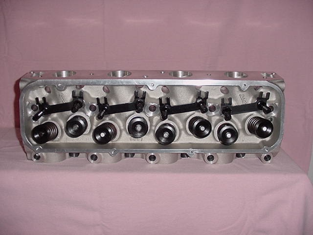
| Bowl pics: |
| The peformer castings come in 3 distinct styles. The first is the Performer RPM, second is the RPM CJ intake port and finally the Victor CJ which is the RPM CJ with roller Valve springs and hardware. All versions start out with the same base castings. |